By Todd Brady and Steven H. Miller, CDT Cold-formed steel framing (CFSF)—also known as ‘light-gauge’—began as a kind of alternative lumber, but after decades of positive performance it has finally come into its own. Much like wood worked by carpenters, steel studs and track can be cut and combined to create more complex shapes. Until recently, however, there has not been any real standardization of assemblies or connections. Each rough opening or other special structural element had to be detailed separately by the engineer of record (EOR). These project-specific details were not always followed by contractors, who may have ‘done it another way’ for a long time. In any case, there has been considerable variation in the quality of field assemblies.
Eventually, familiarity bred discontent, and discontent inspired innovation. New framing elements—beyond standard C-shaped studs and U-shaped tracks—are not only possible using advanced roll-forming methods, but can also be pre-engineered/pre-approved for specific needs to improve CFSF at both the design and construction phases. Lintel Roll Forming Machine

Standardized, code-approved specialty elements can solve many challenges in a consistent manner with better, more reliable performance. They simplify detailing and provide a solution more likely to be properly installed by the contractor. They also speed up construction and streamline inspections, saving time and headaches. These standardized components also improve jobsite safety through less cutting, assembly, screwing, and welding.
Standard practices without standards CFSF has become such an accepted part of the landscape it is hard to imagine commercial or high-rise residential construction without it. This broad acceptance has been achieved in a relatively short time; it did not see widespread use until after World War II.
The first design standards for CFSF were published in 1946 by the American Iron and Steel Institute (AISI). The latest version, AISI S 200-07, North American Standard for Cold-formed Steel Framing–General Provisions, is now the standard for Canada, the United States, and Mexico.
Basic standardization made all the difference, and CFSF took off as a construction method, both for load- and non-load-bearing requirements. Among its benefits, it is:
As ground-breaking as the AISI standard was, it did not codify everything. Much was still left to designers and contractors to decide.
The CFSF system is founded on studs and track. Steel studs, like wood studs, are vertical members. They are usually formed in a C-shaped cross-section, with the ‘top’ and ‘bottom’ of the C forming the narrow dimensions of the stud—its flanges. Tracks are horizontal framing members—sill plates and header members—designed in a U-shape to receive the studs. Studs are generally made in sizes similar to nominal ‘2-by’ lumber: 41 x 89 mm (1 5/8 x 3 ½ in.) is a ‘2×4,’ while 41 x 140 mm (1 5/8 x 5 ½ in.) is a ‘2×6.’ In these examples, the 41-mm dimension is referred to as the ‘flange,’ and the 89- or 140-mm dimension is the ‘web,’ drawing on concepts familiar from hot-rolled steel and similar I-beam type members. The track is sized to accommodate the overall width of studs.
Until recently, stronger members required by the design had to be detailed by the EOR and assembled in the field, using combinations of built-up stud and track, and C- and U-shaped members. The exact configuration was often left to the contractor, and could vary considerably even within one project. However, experience with CFSF over several decades led to identification of the limitations of these basic shapes, and problems associated with them.
For example, water can collect in the bottom track of a framed wall during construction when the framing is exposed. In the presence of sawdust, paper, or other organic material, this can then result in mould or other moisture-related problems, including gypsum board deterioration or the attraction of pests after the wall is enclosed. Similar problems can occur if water infiltrates the completed wall and collects due to condensation, leaks, or spills.
One solution is a specialized track with drainage holes punched into it. Improved stud designs are also being made. They feature innovations such as strategically placed ribs bent into the cross-section that increase stiffness. Textured stud surfaces prevent screws from ‘walking,’ resulting in cleaner connections and more consistent finishes. These small improvements, multiplied over tens of thousands of studs, can make a big difference on a project.
Beyond studs and track Conventional studs and track are generally adequate for a simple wall with no rough openings. Loads can include the weight of the wall itself, finishes and equipment on it, and wind; for some walls, they also include the dead and live load from the roof or floors above. These loads transfer from top track to studs to bottom track, and from there to the foundation or other portions of the superstructure (i.e. concrete decks or structural steel columns and beams).
If there is a rough opening (RO) in the wall—a door, window, or large HVAC duct, for example—the loads from above the opening must be transferred around it. A header must be strong enough to bear the load of one or more so-called cripple studs (and the attached gypsum board) above the header, and transfer it to jamb studs—the RO vertical members.
Jamb studs must, likewise, be designed for greater loads than ordinary studs. For example, at interior locations the opening must be strong enough to carry the weight of the drywall above the opening (i.e. 29 kg/m2 [6 psf] for one-hour walls [one-layer 16-mm (5/8-in.) gypsum each side] or 54 kg/m2 [11 psf] for two-hour rated walls [two-layer 16-mm gypsum each side]), plus seismic loads and, often, the weight of a door and its inertia of operation. At exterior locations the opening must resist wind, seismic, and similar loads.
In traditional CFSF construction, headers and jamb studs are fabricated onsite by building up combinations of standard studs and track into beefier, stronger members. One typical RO header, called a box header, is built by screwing and/or welding together five pieces. Two studs are enclosed by two tracks, and the third track is attached across the top, open side up, to receive the cripple studs above the opening (Figure 1). Another type of box header is made with only four pieces—two studs and two tracks. Another is made with three—two tracks and a stud. The exact method of fabrication of these assemblies is not standardized, but varies among contractors and even workers.
Built-up fabrication is established in the industry, even though it can cause multiple problems. It incurs high cost at the engineering phase because there are no standards, so rough openings have to be individually designed and detailed. Onsite cutting and construction of these labour-intensive assemblies also raises costs, wastes material, increases site waste, and adds jobsite safety risks. Further, it creates quality and consistency issues that should be of special concern to design professionals. It tends to lower the framing’s consistency, quality, and reliability, and may also compromise drywall finish quality. (For an example of these problems, see “Bad Connection.”)
Header systems Connecting built-up headers to studs can also cause esthetic problems. Metal-over-metal overlaps created by tabs on built-up headers compromise wall finishes. Interior wall gypsum board or exterior sheathing may not lay flat over metal tabs with screw heads protruding from them. Bulges in wall surfaces result in a noticeable finish unevenness and the need for extra remedial work for concealment.
One solution for the connection issue is a pre-fabricated clip that is attached to the jamb stud and then receives the header. This approach standardizes the connection and eliminates inconsistencies caused by field fabrication. The clip eliminates metal overlapping metal and protruding screw-heads on the wall surface, improving the wall finish. It also halves installation labour. Formerly, one worker had to hold the header level up while another screwed it in place. With a clip system, one worker installs the clips, and then snaps the header into place on them. The clip is generally made as part of a complete, pre-engineered header system.
The reason for building up several pieces of bent metal into a header is to provide something stronger than a single piece of track to support the wall above the opening. Since bends stiffen the metal against buckling—effectively creating mini-beams within the member’s larger planes—the same result can be achieved using a single piece of metal with a greater number of bends.
This principle can be easily understood by laying a piece of paper across one’s slightly spread-out hands. Initially, the paper buckles in the middle and slips through. However, if it is folded once lengthwise, and then opened (so the paper forms a V-shaped channel), it is less likely to buckle and fall through. The more folds, the stiffer it gets (within certain limits).
Multi-bend technology takes advantage of this effect by adding folded grooves, channels, and returns into the overall shape. ‘Direct strength design’—a new analysis method made practical using computers—has replaced traditional ‘effective width design,’ and enabled the evolution of simple shapes into related, higher-performing configurations that get more strength from the steel. This trend can be seen in many CFSF systems. These shapes, especially when executed in higher-strength steel—390 MPa (57 ksi) instead of the formerly industry standard 250 MPa (36 ksi)—allows a member’s overall performance to be strengthened without significant changes in size, weight, or steel thickness.
In cold-forming steel, another factor comes into play. Cold working of steel, such as making the bends, alters the properties of the steel itself. The worked portions of the steel gain in yield strength and in ultimate strength, and see a reduction in ductility. The portions that are worked the most gain the most. Advances in roll-forming have led to tighter bends, meaning steel laying closest to the bent edge is worked more than in older roll-forming processes. The more bends and the tighter they are, the more steel within the member that is strengthened by cold working, raising the overall strength of the member.
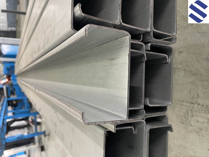
Conventional U-shaped track has two bends; C-shaped studs have four bends. A pre-engineered header in a modified W-shape has 14 bends, located to maximize the portions of the metal actively engaged in resisting load. A single piece in this configuration can be the entire header in a doorframe’s rough opening.
For very wide openings (i.e. more than 2 m [7 ft]) or situations with high loads, multi-bend headers can be stiffened even further by incorporating a mating W-shaped insert. It adds more metal and 14 more bends, increasing the total number of bends in the overall shape to 28. The insert is placed inside the multi-bend header with the W inverted, so the two Ws together form a rough X-shape. The W’s legs function as the top track of the header. They receive the cripple studs above the RO, which are attached with screws. This works with or without the stiffening insert in place.
The main benefits of such a pre-fabricated header/clip system are speed, consistency, and improved finish. By selecting a manufactured header system that is code-approved—such as one with International Code Council-Evaluation Service (ICC-ES) acceptance—the designer can specify components according to load and wall-type fire requirements, and avoid having to design and detail each individual opening, saving time and resources. (ICC-ES, the International Code Council Evaluation Service is recognized by the Standards Council of Canada [SCC]). This pre-fabrication also ensures the rough openings are built as designed, and have consistent structural soundness and quality, without variations introduced by field-cutting and assembly.
Consistency of installation is also increased, since clips have pre-drilled screw holes that leave no doubt about the number and location of connections to the jamb stud. Metal-overlapping-metal connections on the wall plane are eliminated, improving the flatness of the gypsum board finish and avoiding bulges.
Additionally, such systems can have environmental benefits. A single-piece header can use 40 per cent less steel than built-up members. Since it does not require welding, it eliminates the associated toxic gas emissions.
Wide-flange jamb studs Conventional jamb studs are built up by joining—screwing and/or welding—two or more studs together. While strong, they can cause their own problems. They are much easier to assemble before installation, especially if they are being welded. However, that seals off access to the part of the stud that gets attached to the hollow metal frame (HMF) doorway.
One solution is to cut holes through one of the studs to make frame attachments from inside the stud assembly. However, this can present difficulties in inspection and cause additional work. It has been known to prompt an inspector to insist the HMF be connected to half the jamb-stud and inspected, and then have the second part of the double-stud assembly welded together in place. This halts all work around the door opening, can delay other trades, and calls for increased fire protection because of in-situ welding.
Pre-engineered wide-flange studs, designed specifically as jamb studs, can be used instead of built-up studs, saving considerable time and materials. The problem of access for attaching to HMF doorways is also resolved, since the open side of the C provides continuous access and easy inspection. The open C-shape is also accessible for full insulation, where built-up headers and jamb studs often create a 102- to 152-mm (4-to 6-in.) void in the insulation around the doorway.
Top-of-wall connection Another area of design benefitting from innovation is the top-of-wall connection to the deck above. Due to the changing deflection of the deck under different loading conditions, the distance from one floor to another can vary slightly over time. In a non-load-bearing wall, a gap must be left between the top of the studs and the deck; this allows the deck to move down without crushing the studs. The deck must also be able to move up without ripping the studs apart. The gap is a minimum of 12.5 mm (½ in.), being half of a total movement allowance of ±12.5 mm.
Two traditional solutions have dominated. One is to attach a track with long legs—50 or 60 mm (2 or 2.5 in.)—to the deck, with the stud top ends simply inserted in the track but not secured. To prevent the studs from twisting out of alignment and losing structural value, a piece of cold-rolled channel is inserted through knock-outs in the stud at 150 mm (6 in.) or less from the top of wall, a time-consuming process not popular with contractors. To cut corners, some contractors may even omit the cold-rolled channel—leaving the studs parked in the track with nothing to keep them secure or aligned. This violates ASTM C 754, Standard Specification for Installation of Steel Framing Members to Receive Screw-attached Gypsum Panel Products, which states studs must be attached to tracks with screws. When this departure from design is not discovered, it can compromise the quality of the finished wall.
The other widely used solution is double-track construction. A standard track is placed across the top of the studs and each stud is screwed to it. A second, customized, wider track is placed over the first, and is attached to the deck overhead. The standard track can slip up and down inside the custom track.
This approach has three disadvantages:
Several solutions have evolved for this challenge, all involving a specialized piece that allows a slotted connection. Variations include types of slotted track, or slotted clips to attach track to deck. The slotted track variation, for example, is fixed to the underside of the deck using a fastening method appropriate to the particular deck material. Screws through the slots are attached to the tops of studs (in compliance with ASTM C 754), allowing the connection to float up and down within a range of about 25 mm (1 in.).
In fire-resistive walls, this floating connection must be fireproofed. Underneath a fluted, concrete-filled steel deck, the fireproofing must be able to fill uneven spaces under the flutes and maintain its firestop function as the distance between the top of wall and the deck varies. Assemblies for this connection are tested according to a new standard, ASTM E 2837-11, Standard Test Method for Determining the Fire Resistance of Continuity Head-of-wall Joint Systems Installed Between Rated Wall Assemblies and Non-rated Horizontal Assemblies. This standard is based on Underwriters Laboratories (UL) 2079, Tests for Fire Resistance of Building Joint Systems.
A benefit of using a specialized top-of-wall connection is it may include standardized, code-approved, fire-resistive assembly details. A typical assembly places fire-resistive materials up against the deck, and draping down around the top of the wall on both sides for a few inches. Just as the wall is free to slide up and down in the slotted attachment, it also slips up and down within a fire-resistive assembly. Materials of this assembly could include mineral wool, cementitious structural steel fireproofing, or gypsum board, used separately or in combination. Such systems must be installed as tested, approved, and listed in directories like that of Underwriters Laboratories of Canada (ULC).
Conclusion Standardization is the foundation of all modern construction. It is ironic that, in the case of cold-formed steel framing, ‘standard practices’ have had very little standardization, and that innovations which break with those traditions are also the creators of standards.
Using these standardized systems protects both designer and owner, saving considerable time and expense, and also improving site safety. They bring a consistency to construction, and are more likely than built-up systems to be constructed as designed. CFSF, with its combination of light weight, sustainability, and affordability, is likely to increase its share of the construction market, doubtless driving further innovation.
Todd Brady is president of Brady Construction Innovations, inventor of the ProX Header Rough Opening system and Slp-Trk head of wall solutions. He is a metal stud framing expert with 30 years of field and contracting experience. Brady can be contacted via e-mail at bradyinnovations@gmail.com.
Steven H. Miller, CDT, is an award-winning writer and photographer specializing in issues of the construction industry. He is creative director of Chusid Associates, a consulting firm providing marketing and technical services to building products manufacturers. Miller can be reached through www.chusid.com.
Solar Strut Channel Mounting Brackets Roll Forming Machine Your email address will not be published. Required fields are marked *